|
AT8575C
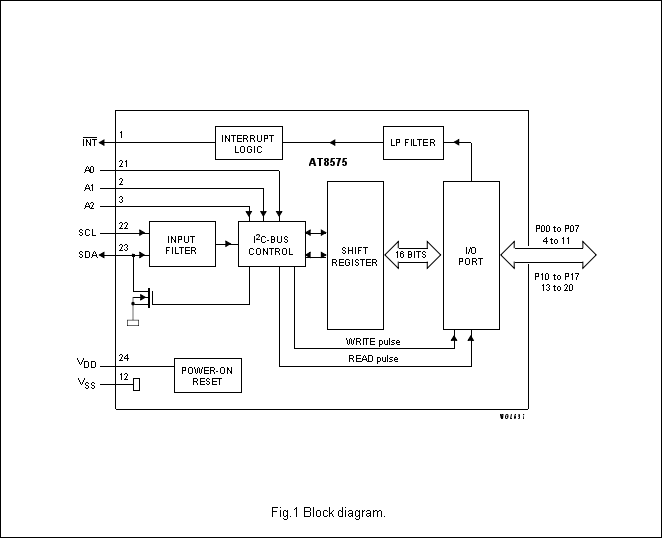
DESCRIPTION The device is a silicon CMOS circuit. It provides general purpose remote I/O expansion for most microcontroller families via the two-line bidirectional bus (I2C-bus).The device consists of a 16-bit quasi-bidirectional port and an I2C-bus interface. The AT8575C has a low current consumption and includes latched outputs with high current drive capability for directly driving L EDs. It also possesses an interrupt line (INT) which can be connected to the interrupt logic of the microcontroller. By sending an interrupt signal on this line, the remote I/O can inform the microcontroller if there is incoming data on its ports without having to communicate via the I2C-bus. This means that the device is an I2C-bus slave transmitter/receiver. Every data transmission from the AT8575C must consist of an even number of bytes, the first byte will be referred to as P07 to P0O and the second byte as P17 to P10. The third will be referred to as P07 to P0O and so on. FEATURES
BLOCK DIAGRAM
|


