Home > Products > AT8023
AT8023
Part Number Description Timing current (typical) Clock format Integrated crystal Temperature compensation Bckup power Trickle charge Alarm / Interrupt Square wave output (Hz) Clock calibration function Power down User RAM (bytes) Working temperature range (℃) Cross Reference Oscillation stop detection Power supply voltage (V) Pin/Package
AT8023 0.45μA (3V) HH:MM:SS Periodic Interrupts / 2﹣A 32K (push-pull) -40 to +85 R2023 1.0~5.5 TSSOP10G,FFP12,QFN023023-16

DESCRIPTION

      The AT8023 is a CMOS real-time clock IC connected to the CPU by two signal lines, SCL, SDA, and configured to perform serial transmission of time and calendar data to the CPU. The periodic interrupt circuit is configured to generate interrupt signals with six selectable interrupts ranging from 0.5 seconds to 1 month. The 2 alarm interrupt circuits generate interrupt signals at preset times. As the oscillation circuit is driven under constant voltage, fluctuation of the oscillator frequency due to supply voltage is small, and the time keeping current is small (Typ. 0.45 μA at 3 V). The oscillation halt sensing circuit can be used to judge the validity of internal data in such events as power-on; The supply voltage monitoring circuit is configured to record a drop in supply voltage below two selectable supply voltage monitoring threshold settings. The 32.768 kHz clock output function (CMOS output with control pin) is intended to output sub-clock pulses for the external microcomputer. The oscillation adjustment circuit is intended to adjust time counts with high precision by correcting deviations in the oscillation frequency of the crystal oscillator. Since the package for these ICs are TSSOP10G (4.0 x 2.9 x 1.0: AT8023T) or QFN023023-16 (2.3 mm x 2.3 mm x 0.4 mm: AT8023L), high density mounting of ICs on boards is possible.

FEATURES

  • Minimum Timekeeping supply voltage: Typ: 0.66 to 5.5 V (Worst: 1.00 V to 5.5 V); VDD pin

  • Low power consumption: 0.45μA Typ at VDD = 3 V (1.00μA Max.)

  • Two signal lines (SCL, SDA) required for connection to the CPU.

  • Time counters (counting hours, minutes, and seconds) and calendar counters (counting years, months, days, and weeks) (in BCD format)

  • Interrupt circuit configured to generate interrupt signals (with interrupts ranging from 0.5 seconds to 1 month) to the CPU and provided with an interrupt flag and an interrupt halt

  • 2 alarm interrupt circuits (Alarm_W for week, hour, and minute alarm settings and Alarm_D for hour and minute alarm settings)

  • With Power-on flag to prove that the power supply starts from 0 V

  • 32-kHz clock output pin (CMOS push-pull output with control pin)

  • Supply voltage monitoring circuit with two supply voltage monitoring threshold settings

  • Automatic identification of leap years up to the year 2099

  • Selectable 12-hour and 24-hour mode settings

  • High precision oscillation adjustment circuit

  • Built-in oscillation stabilization capacitors (CG and CD)

  • Package:  TSSOP10G (4.0mm x 2.9mm x 1.0mm: AT8023T)

  • FFP12 (2.0mm x 2.0mm x 1.0mm: AT8023K)

  • QFN023023-16(2.3mm x 2.3mm x 0.4mm:AT8023L) :

  • CMOS process

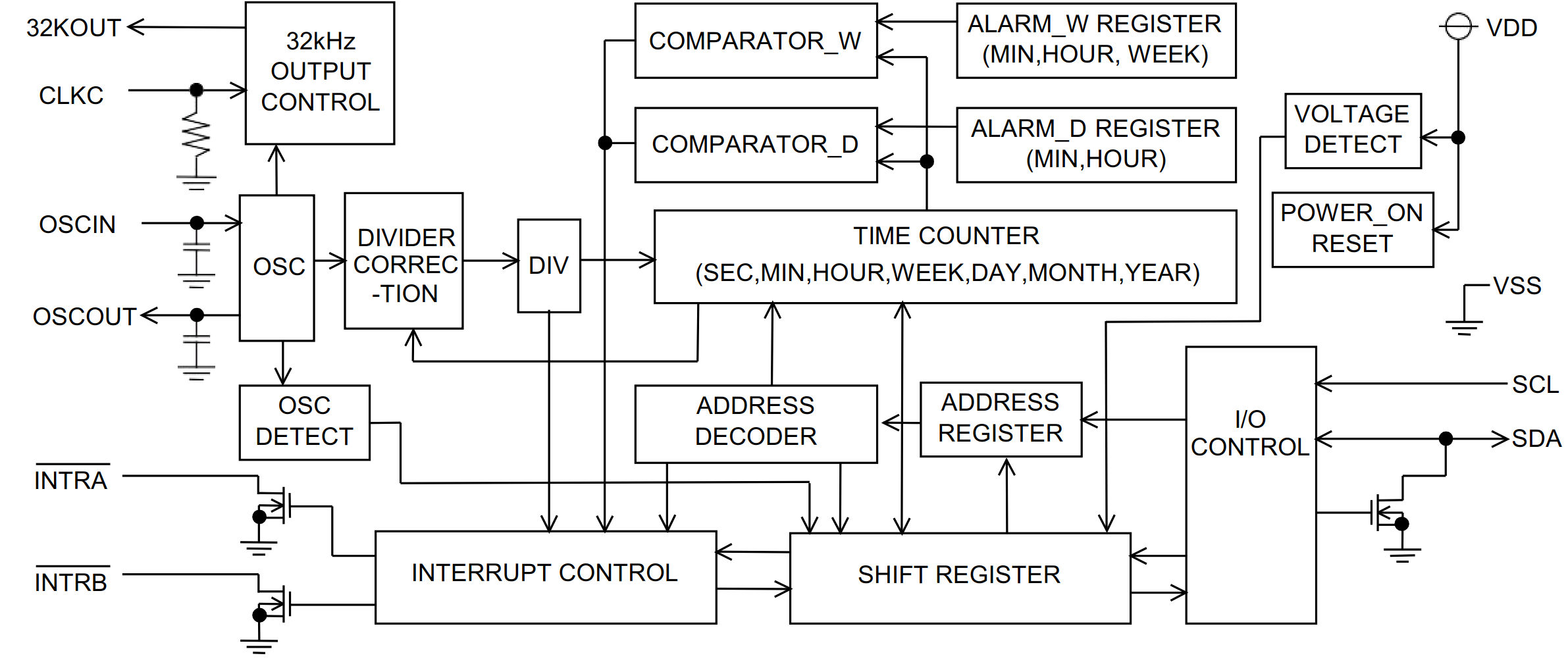
BLOCK DIAGRAM

QQ图片20200914163536.png


Support:万广互联 Copyright © 2008-2020 Analog Tek Technology Co, Ltd 鄂ICP备20005446号-1